I remember being a child and building a space station (it looked a bit like StarLab so I guess the station in general was on TV or in a book) with a solar array that shape, my parents were a little angry and asked where that shape came from. I didn’t have a clue so I basically just said I liked the symmetry. They told me that’s a "very bad shape and that I have to rebuild it. It ended up being 8-shaped, which was also nice.
I was feeling the same :D.
Boy, because of 500c you made me do all that? I was feeling like the Crimson Fleet treated me nicer here.
Maybe this: https://www.microchip.com/en-us/product/PCI11400 Unfortunately to access the whole datasheet you might have to sign an NDA (and probably have a large company), also designing things with those kinds of interfaces isn’t trivial.
Alternatively maybe this: https://www.renesas.com/us/en/products/interface/usb-switches-hubs/upd720202-usb-30-host-controller It also seems to be locked by an NDA.
I just looked I to a scope that can handle USB speeds (my cheap-ish Siglent one can’t) because I’m developing a board with USB 3.1. Now I’m like "nah, it hopefully just works, if it doesn’t, I’ll have no clue why".
They are called soft termination, I’m not sure if that’s available for every component, it came to my attention on ceramic caps. It’s a dedicated feature you can filter components e.g. on Digikey.
I’d say that’s a version of a soft termination capacitor. They are used when there’s risk the board is flexed or exposed to mechanical or thermal shocks to prevent cracks in the capacitor (causing it to fail short).
I’m not sure where to place it but I guess I’ll buy it 🤷🏻♂️. Looks really nice to me :).
I also have that guy :)
Not sure if that helps your research. We have an (very expensive "upper 4 digit region" they didn’t tell me exactly) DJI drone (an Matrice 30T if I remember correctly) at work that has the option of operating autonomously with a base-station where it also automatically lands and recharges. The catch is it’s like impossible to operate autonomous UAVs here because of airspace restrictions (that’s why we only have the "manual" version without that base-station thingy). I’m not directly involved in the department that operates the drone so I don’t have more in depth insights but maybe that already helps a little.
Fun fact, our military had to cancel a large and very expensive drone program because the drone (a little larger one tho) couldn’t get certified in European airspace ("Eurohawk" if you want to google that). So I’m not sure how easy it will be to hack something together depending where you are in the world and what restrictions say there.
I did it somehow expect to be even more expensive, so I’m not that shocked.
I’m sure https://lemmy.world/c/pcmasterrace can help :)
Wet sanding (with appropriate sandpaper) makes a huge difference, especially for smaller grid sizes.
But it’s probably easier to just get some individual pieces from Bricklink.
Yeah it actually won’t work, I initially thought it would but after having a closer look, it won’t.
By having a closer look I’d say the pinout in general matches but the "wings" aren’t attached in a suitable position, they would have to be rotated 90°:
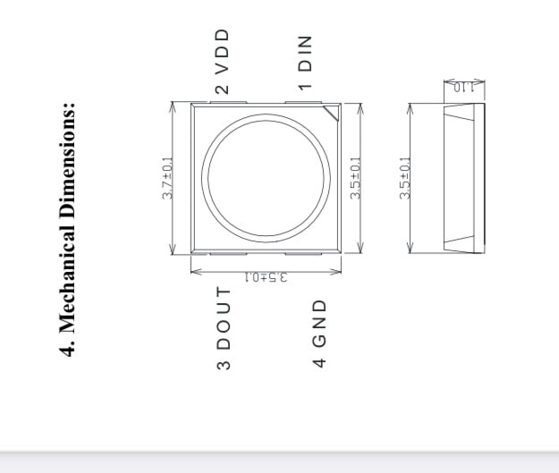
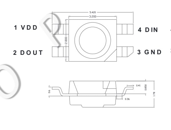
It seems "top" is in both cases the end where the light shines out, so the are both basically mounted top down.
Hm, aren't the reverse-mount LEDs that you mentioned an option? The pinout seems to match after having a quick glance at the (Chinese) datasheet. E.g. from here: https://www.lcsc.com/mobile/product-detail/Light-Emitting-Diodes-LED_OPSCO-Optoelectronics-SK6812MINI-EA_C5378731.html
I actually designed the other things myself, you can find them on my printables profile: https://www.printables.com/@theo/models :)
I’d probably ask myself first if there is any chance at all that the vessel is found in any time in the near future. I mean the titanic is substantially bigger and was found like 70 years after it sunk.
I somehow have the impression that there weren’t many thoughts wasted on safety (systems) :(
If it sounds too good to be true, it usually is.
It’s not really missing, there’s some life-insurance fraud going on.
The first double sided board I made at home :)
I’m currently working on a more complex project that uses double sided assembly (and a weird USB-C connector). To practice these things a little, I ordered some low cost boards to get used to that connector and explore double sided reflow (which seems easier than I expected).
For those who are interested, this is a reference design from framework computer for their expansion card system. It can be programmed with circuitpython or Arduino and utilises a SAMD21 microcontroller.
A part of my shelf-city :)
I created a little shelf-city over time that is connected with a monorail line.
This is Trixie :)
Say hello to Trixie :). She’s around eight years old and got here as a young kitten after being left in a cardboard box on the side of the road and my ex-girlfriend brought her here. Girlfriend of that time left, Trixie stayed and lives here since then.
Best technique to solder (USB-C) edge connectors?
Hello :). I have some of these Molex 1054440011 USB-C edge connectors/plugs of that I somehow don’t know what’s the best way to assemble them onto my PCB.
I have the pads (standard layout from the datasheet drawing) exposed on the stencil but the pins push the paste away a little so I had quite an amount of solder bridges to rework after reflowing them. Could probably a little less solder paste (so smaller openings) and/or differently shaped stencil openings help? Also there are pins (and other components) on the backside so it’s difficult to apply paste accurately on both sides. The pins are additionally a little weirdly shaped (they bend upwards at the ends so it’s easier to push the PCB between the pins) what makes them less accessible with a soldering iron and the 0.5mm pitch doesn’t make things easier. At least the tension of the pins holds the connector in place while reflowing.
This specific one will primarily only be a one (or two)-off prototype board so I could life with some reworking but maybe someone around here has experience with these things. I also wondered how something like that would be assembled in a larger scale, the pins hold the PCB quite tight between them, I can’t imagine a pick-and-place machine could handle that.
Thanks for reading this post and maybe you have some answers :).