Search
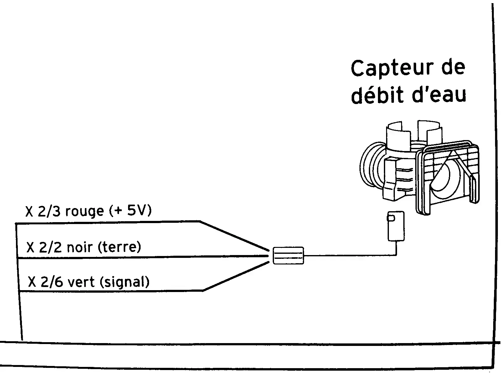
help needed to understand this diagram of a water flow sensor (from a boiler)


cross-posted from: https://lemmy.dbzer0.com/post/26703241
> This diagram is from the service manual of a combi boiler. It’s a flow sensor which detects whether hot water is running, which is then used to trigger on-demand heat and switch a diverter to take radiators out of the loop. > > In English, the diagram shows: > * X ⅔ red wire (+5V) > * X 2/2 black wire (ground) > * X 2/6 green wire (signal) > > I need to know what those fractions mean. I took the voltage measurements in this video: > > * https://iv.ggtyler.dev/watch?v=d8ucufoyUlQ > > I cannot necessarily trust the model in that video to have the same specs as mine. My voltmeter detected 4.68 V on the red input wire showing that the sensor is well fed. The green “signal” wire is supposed to be 0 V at rest and 2 V with water running (or I think the reverse of that is used in some models). In my case the green wire is ~1.33 V at rest and ~0.66 V when water is running. I need to know if these readings are normal as I troubleshoot this problem.
update --- @[email protected] and a couple others gave the answer I was after. Then @[email protected] helped solve the underlying problem. The theory that the sensor was fine but the board was not drove me to test the sensor in isolation. The sensor gave correct output in isolation. Then I connected it back to the motherboard to retest and reconfirm that it’s still broken. But it actually worked. The hot water suddenly and mysteriously works now. I guess the act of draining the water and unplugging the connector then reconnecting and repressurizing caused it to work. It may be temporary, since in the past it was hit or miss whether it would work.
A pull-up resistor increases the low side of a signal, how can I counteract it?
I have an ebike computer that has two inputs that accept square wave signals. The range is 0-5V. One of the inputs has no pull-up/down resistors on it. When I hook up a device producing signal, the

Solution
Using an open drain buffer like the 74LVC1G07 did the trick. Note that this part only works for inputs with a pull-up resistor. There are other parts from the same lineup that can work with any input.
Problem
> I have an ebike computer that has two inputs that accept square wave signals. The range is 0-5V. One of the inputs has no pull-up/down resistors on it. When I hook up a device producing signal, the signal is detected correctly. Both highs and lows are detected correctly. The other input has a built-in pull-up resistor. When I hook the same signal to it, only the high side is detected. Measuring the voltage of the low side, it's a bit higher than when hooked to the other input and I'm guessing it isn't crossing the low threshold the computer expects in order to register the low.
> Am I right in thinking that the pull-up resistor is increasing the lows?
> Is it possible to counteract the internal pull-up resistor by hooking a pull-down resistor to the input?
> I'm a software guy with decent soldering skills and minimal knowledge in electronics so please answer like I'm not the brightest electronic bulb on the tree.
> Thank you in advance!
Cross-posting my question from StackExchange.